Wing


  • Completing fuel tanks
    Fuel Tank Section 18 Wing
    Apr 3, 2022

    Closing up the fuel tanks went relatively smoothly after a little planning, and watching over the video that Vans produced several times. I found that I could only do about 2 ribs in a row to stay within the working period of the proseal, which included mixing the proseal, apply it to a rib, get the rib seated and cleco'd into the tank, rivet the rib, and doing the final fillet / smoothing around edges, and sealing off the shop heads.

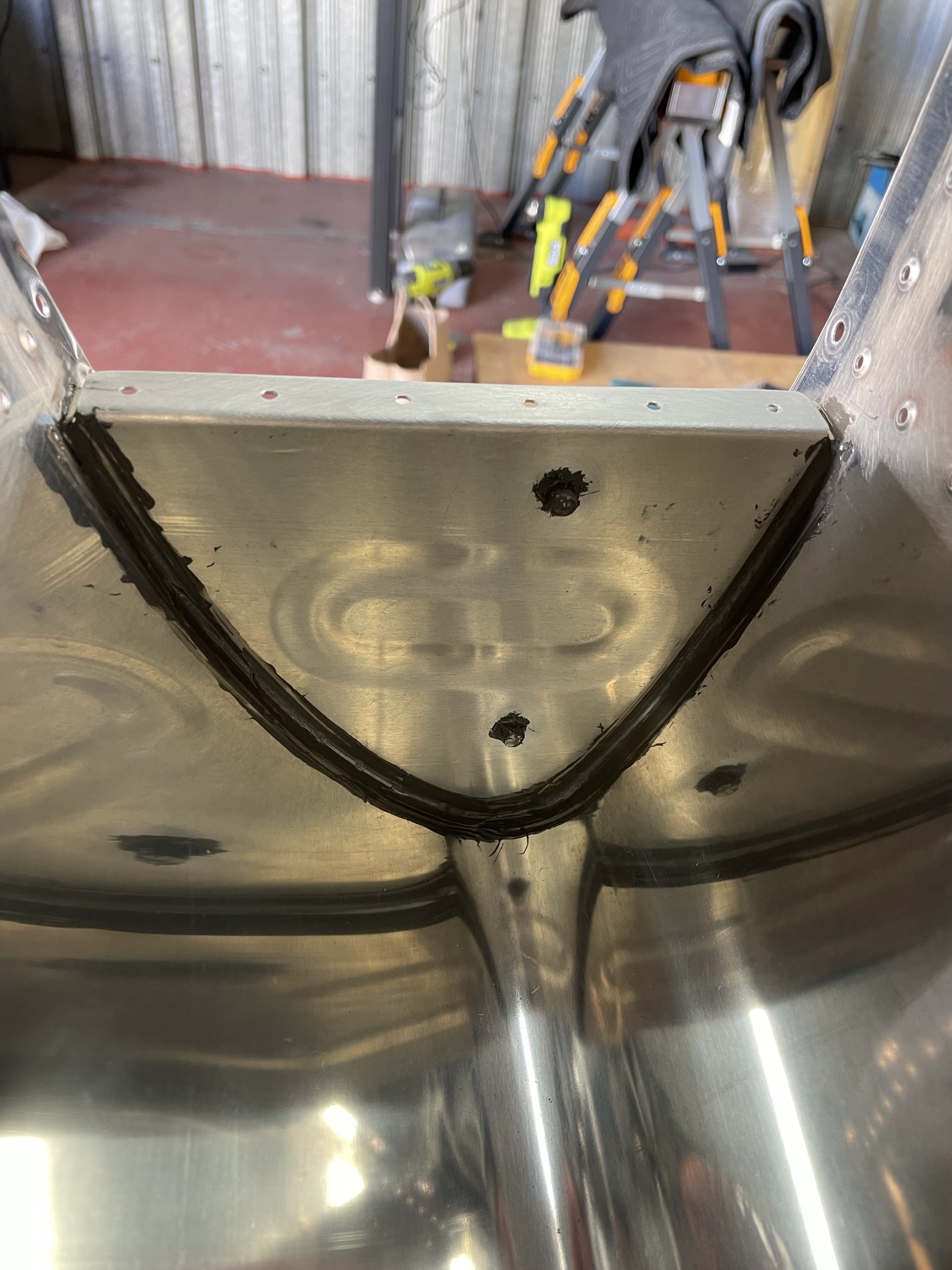
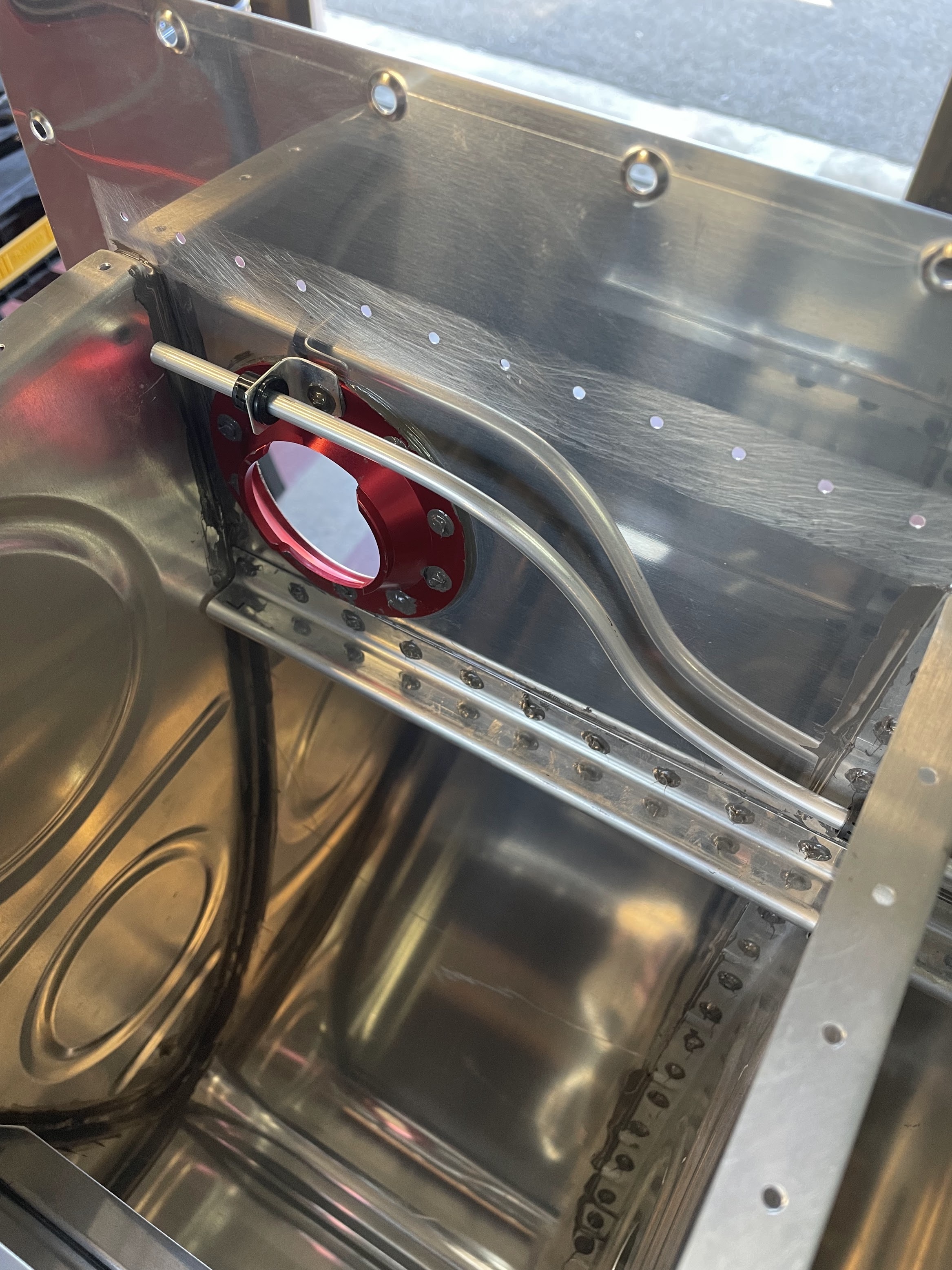
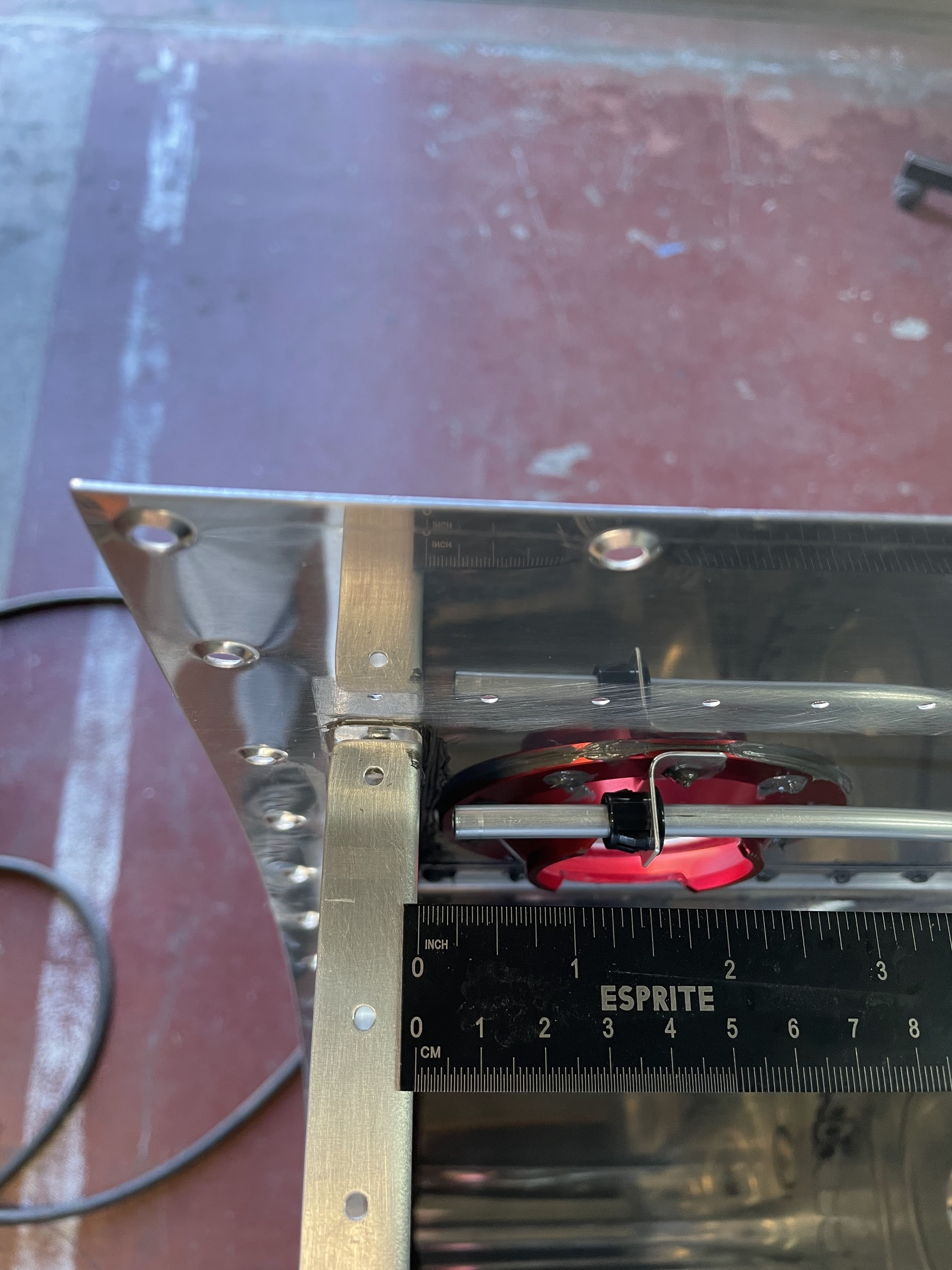
    There were two places in particular that gave me problems that I would probably have done differently if I were to do it again. The first was the inboard external ribs that butt against the tank attach bracket. This area has a lot of mating parts, and on both tanks I noticed a small leak due to insufficient sealant between the skin and the bracket flange. Simply tracing a heavy fillet between the skin and the mating parts was insufficient for sealing this area. I ended up having to drill out many of the rivets in this area, and get creative trying to press sealant under the skin to get it sealed. In hindsight I would have just slathered all the flanges in sealant and dealt with the resulting mess. The other problem area was the float sensor. This is attached with 5 screws, and I'm still unsure if I need to seal the threads of the screws, or can seal it at the head - although this can easily be addressed afterwards and doesn't need any disassembly of the tank.

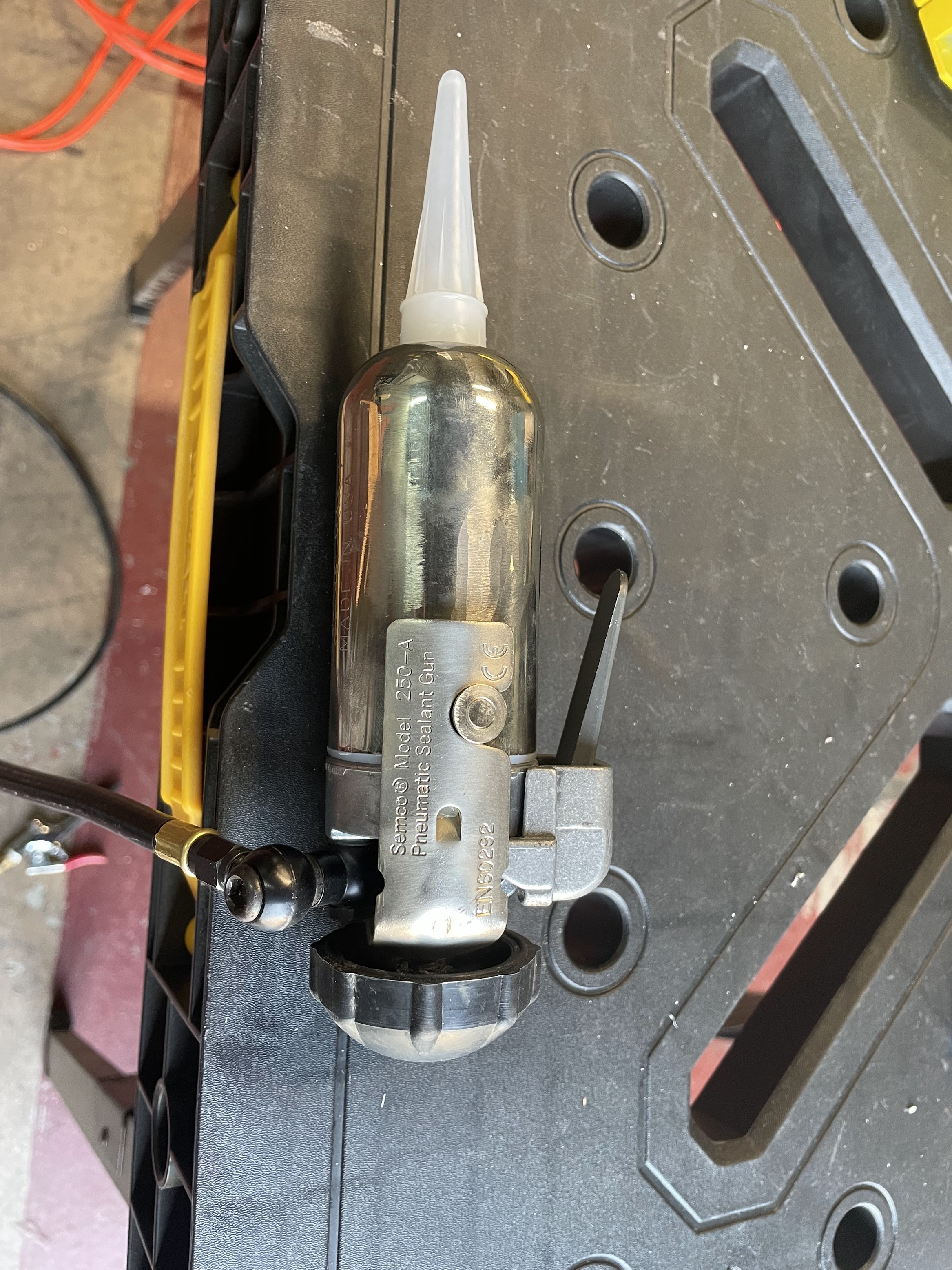
    Getting the back bulkhead in place went a bit better than expected. Using the semco gun helped quite a lot here, and laying an even continuous bead along the entire flange was actually quite easy.

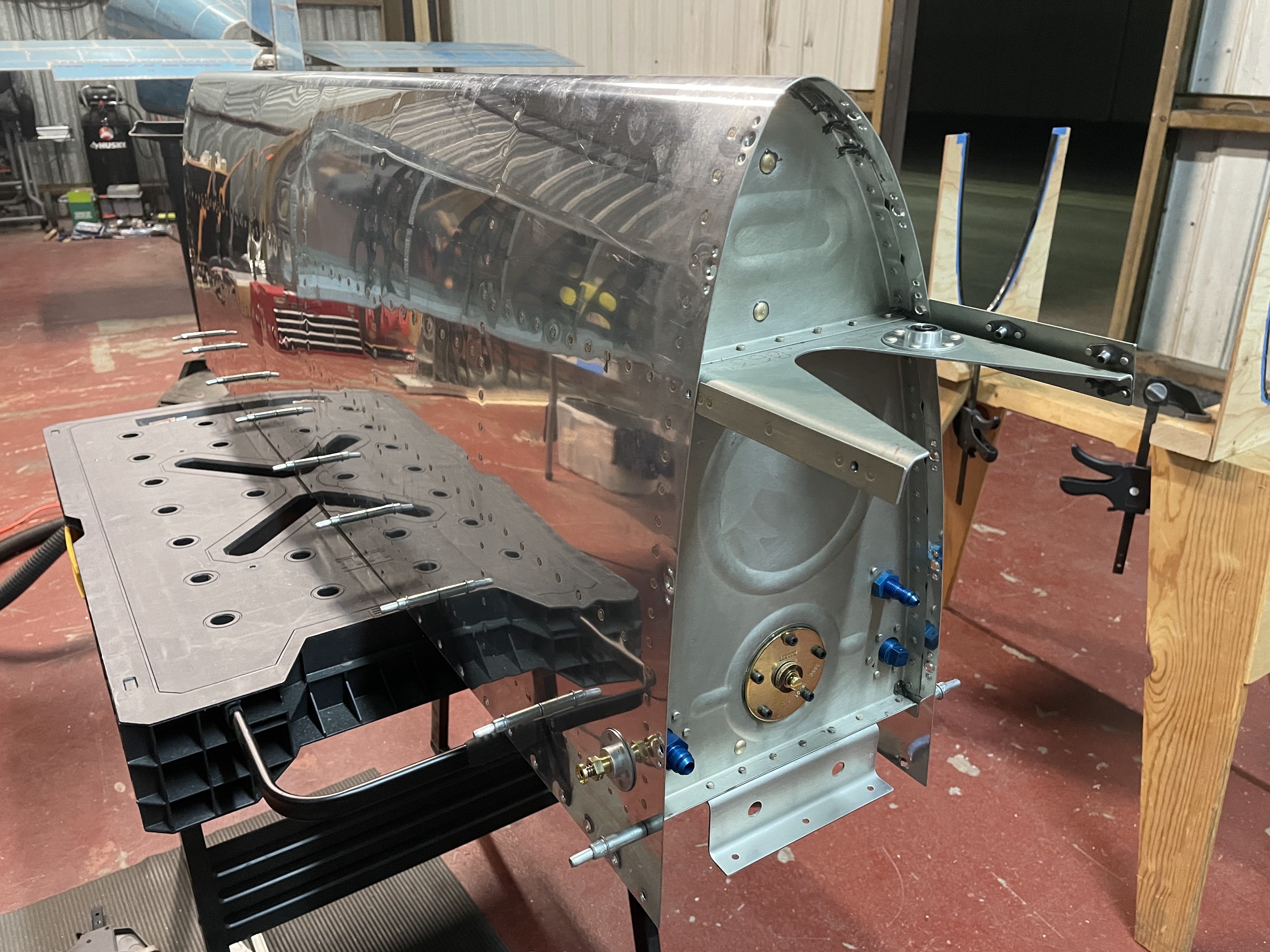
    Lastly the nervous moment of leak testing the tanks. It took several iterations of trying to tie the balloon to the fitting in a way that didn't leak right where the balloon attaches. I found that a tight rubber band seemed to do the trick. I did find a tiny pinhole at the fuel drain fitting in one tank, and a small leak in both tanks in the exact same location at the point the tank attach brackets mate with the skin. Everything was fixed, and both tanks were able to hold pressure without any noticeable change in the balloon size for at least 2 weeks. Fingers crossed that means they're leak free and robust.


  • Starting fuel tanks
    Fuel Tank Section 18 Wing
    Nov 25, 2021

    I had been putting off working on the fuel tanks for the better part of 6 months, and coincidentally have had a container of proseal sitting in the fridge for about 6 months. The impeding expiration of the sealant has created the necessary inspiration to get this one finished.

    Vans has created a wonderful walkthrough for tank construction here that has helped a lot with visualizing many of the steps as well as a bunch of good tips on technique.

    First step was all the standard material prep. I took extra care on getting all the flanges at 90-degrees, and fluting to keep the rivet lines on the ribs as straight as possible.

    When drilling out the strainer flange, it probably didn't matter that they are perfectly symmetric, but I clamped the L and R ribs together and drilled them as one. Dimpling the forward rib did indeed requires a pop-rivet style dimple die as documented.

    I decided to prime every surface that is not internal to the tank, which included the outside sides of the solid ribs, the back side of the rear baffle, and part of the tank stiffener.

    On to the proseal! First observation: while it is indeed super sticky and gets on everything if you let it, it's actually not that bad to work with, and does clean off quite easily with a little acetone. All together, I'm not sure why there is so much apprehension about it among builders.

    I masked off all the surfaces to be scuffed, and started with the stiffeners, fuel cap, and drain fitting. Essentially using the technique described in the Vans video, everything went pretty much as expected with back-riveting. I did purchase this thin-nose yoke to make riveting the fuel caps easier. Not sure if it's quite worth $150 for setting 20 rivets, but I'm sure I'll have uses for it in the future. I really didn't want to use the rivet gun to set these with the skin being so floppy.

    For sealing the shop heads, I didn't have any spare aluminum tubing as described in the Vans video, but I did have a hex screwdriver bit adapter that comes with every cheap set of drill bits that seemed to work just as well.


  • Completing ailerons
    Aileron Section 22 Wing
    Sep 19, 2021

    The main skin of the ailerons go together pretty quickly, and being able to back-rivet all the stiffeners and end ribs makes it rather easy. Riveting the top skin to the spar also went together really nicely, using a bucking bar that is slightly angled such that it can rest against the far end of the spar flange. I used some spare j-channel and clamp-style clekos to keep the trailing edge straight while riveting the skin to the spar.

    The big oops moment here was due to the counterweight in the leading edge being the significant portion of the mass, but extends only about 2/3 the length of the aileron. As such, the part is significantly heavier on one side although it doesn't look like it would be. I had the aileron sitting square in the cradle, which was positioned at about the 1/3 and 2/3 points lengthwise. While riveting the top skin of the heavy end, which was extending outside the width of where the cradle was positioned, the added weight of the bucking bar and the forces of riveting caused the lighter side of the part to lift out of the cradle. This caused the location where I was riveting to drop an inch or two before I caught the part from falling, but unfortunately caused the rivet gun to pound a few impressive dents in the delicate skin on the way down.

    After some cursing and swearing, I decided to drill out all the spar rivets attaching the skin, and assess if I could flatten out the dents once the skin was isolated. I purchased a set of dent removal punches from Amazon, and spent half a day tapping and pounding on the dent. In the end, I was able to get it pretty flat, but because the material was already quite thin and only made thinner in that region, there was still a concave deformation that I simply couldn't remove. In reality, I probably could have just used some filler and painted over it in the end, but it bothered me enough that I didn't want to keep it. Especially since it was in a prominent location on the upper surface of the aileron and I know I would notice it. I ordered a replacement skin from Vans, and proceeded to drill out all the stiffeners and ribs from the skin. I was actually surprised how cheap the new part was; I assumed since i was so large that it would cost a ton for the part and shipping, but it was only about $25 shipped since it could be rolled up. If I had known that up front, I would have just ordered the part immediately and had not bothered at all trying to repair the dent.

    The next challenge was the end ribs. These required AN470AD4 rivets, that in particular on one end had almost no space to work with on the forward side. The space was limited by the two hinge brackets, and I puzzled a bit on how to get a rivet in there. If I put the manufactured head on the aft side, it would be possible to get a really narrow bucking bar between the hinge brackets, but I would need a rivet set that was a solid 18" long to reach; and I didn't own such a rivet set or bucking bar. If the manufactured head was on the forward side, the rivet set was too large to fit between the brackets, and even if it did, the rivet holes were not centered between the brackets.

    At this point, I had to consult the internet from build logs of other fellow builders, and thankfully some good solutions here. In the end I pulled out the angle grinder and ground down one side of my offset rivet set. I hate damaging or modifying my tools, but I figured the tool isn't that expensive if I needed to replace it, and it likely would function just fine after the modification. In the end this worked really well, and I think the rivet set still functions just fine for future use. The only down side was that getting it aligned was still rather challenging, and I did make a few small smiley indentations an almost all the rivets, but to the best of my knowledge it's cosmetic, and I buffed them out and moved on.

    The plans call for aligning the "D-cell" of the leading edge to be square before closing it out by riveting the bottom skin. I used a digital level and a short piece of wood as a straight surface to reference against the skin. After going from one end to the other probably 50 times I realized that the skin was fundamentally too flexible to give any reading more precise than about 1 degree, so I finessed angles by torquing the leading edge as best I could within that threshold.

    Riveting the bottom skins was definitely working in confined spaces. I have fairly small hands, and I don't see how anyone who has large hands could possibly do this. The bucking bar that I had only squeezed between the flanges of the spar with about 1/2 inch of working room, and the top and bottom skin press together pretty tightly to make this a pretty tedious job.

    Last was the trailing edge. I reused the 3D printed jig that I made for the flaps to countersink the trailing edge, which worked like a charm. I'm not sure if I mismanaged my stock, but realized I only had a single piece of trailing edge that was long enough for the entire part. For the right aileron, I had to join 2 pieces together. Since this was already in the plans for the flaps, I didn't have a problem doing this here.

    Riveting the trailing edge was done on a back-rivet plate. I simply used the largest diameter back-rivet set I own, and drove the shop heads all the way down to the material while trying to avoid damaging the skins with the rivet set. With a little practice, this worked pretty well and the manufactured heads ended up pretty flush with a surface finish that looks pretty reasonable to me.

    The final product came out quite straight, as about as square as my digital level can sense, so broadly speaking pretty happy with the part. Now the attention goes back to starting the fuel tanks that I've been putting off!


  • Aileron leading edge assembly
    Aileron Section 22 Wing
    Sep 19, 2021

    The aileron leading edge assembly goes together pretty simply. The first minor issue I ran into was that the leading edge holes that are drilled into the stainless steel counterbalance only line up in one orientation of how the counterbalance bolts up to the leading edge A-1004-1 ribs. I somehow managed to flip the counterbalance around after I already match drilled one hole, and now I have an extra hole in the counterbalance unfortunately.

    The other item to note is that the stainless steel is pretty hard to cut through. I ended up using some tool oil when drilling, and still manage to toast at least one bit. The bits also tended to walk a lot, despite center punching the match-drill location. Fortunately, everything was final drilled to a considerably larger size, and any initially oval-shaped match-drilled holes did become true after final drilling.


    The last item of note was that the leading edge skin wanted to bend out a lot when placed on the cradle when assembling the forward portion of the aileron. I ended up having to tape it in several places in fear that it would crease itself given how extreme the bend was.


  • Aileron prep
    Aileron Section 22 Wing
    Sep 19, 2021

    Started with cutting all the stiffeners out, collecting all the parts, and getting everything primed. I find priming such a hassle between part prep/scuff/clean, setting up the spray area, getting the HVLP gun set up, getting primer poured and mixed, and resulting cleanup, that I try to do as much at once as I can. This time I think I got everything without missing a part. It's always super annoying to have some tiny component at the end that I forgot to prime. Makes me wish I used the rattle can zinc chromate sometimes instead of the P60G2 just for the convenience. For those using epoxy primers, it seems even a larger hassle.

    Right off the bat, I managed to over-countersink the inboard hinge brackets. I love the single-flute countersink cutters in that they produce a really clean cut, but they bite so much into the material if you don't set the countersink cage to a shorter depth than you need it's pretty easy to have it pull way too far into the material. I thought for a moment that I could just rivet and move on, but it was inset deep enough that I didn't feel comfortable with it, and ordered a new part from Vans. They were super fast, however, and got me the replacement in a week.


  • Final flap assembly
    Flap Section 21 Wing
    May 10, 2021

    Getting the trailing edges cut and trimmed to butt together perfectly took a little bit of time using hand tools, but pretty happy with the result.

    Much of the flap assembly required to cleco the entire assembly together to final drill, then disassemble for cleanup. I ended up 3D printing a spacer for the hinge brackets to avoid putting in appropriate washers during assembly.

    I used the squeezer to double-flush rivet the hinge brackets. They didn't come out quite as pretty as I was hoping, but look pretty flush in the end.

    For the final riveting of the trailing edge, the instructions didn't provide much information on. I ended up back riveting all the trailing edge rivets, which worked quite well. The only trick was to initially drive the rivets along the axis of the rivet, then finally setting them parallel to the trailing edge.

    The final flap turned out pretty square along both the hinge and the trailing edge.


  • Flap tool fabrication
    Flap Section 21 Wing
    May 10, 2021

    In the flap plans, there are a few callouts to fabricate tools and jigs to countersink and drill the trailing edge at a precise angle. While outright precision probably isn't necessary here, I decided to hop on the CAD and 3D print all these parts instead of fabricating them out of aluminum.

    One challenge was machine countersinking the trailing edges. I noticed that Cleveland Aircraft Tools sold a jig to hold the trailing edge at the right angle to use a countersink cage with. $42 seemed like a lot for such a simple part, and I decided to draw one up and 3D print it also, which worked great.


  • Flap prep
    Flap Section 21 Wing
    May 10, 2021

    While the flaps seemed fairly straight forward, there were a few new and interesting tidbits in the plans that haven't come up in previous parts. First was the use of duck-bill pliers to eliminate "pucker" in the ribs. I didn't actually own any duck-bill pliers by that name, but had a small pair of flat (non-grooved) surface pliers that I put some tape over to not damage the aluminum and straightened out the bend as best I could. It was pretty subtle to start with, but it came out slightly more flush so I suppose mission accomplished.

    And "pucker removed"!

    Next were the inboard leading edges that required doublers and a large nutplate. Pics still need to be deburred, but everything went together nicely.


  • Wing spar nutplates and countersinking
    Section 13 Wing
    Nov 25, 2020

    When match drilling the J-channels against the wing spar, the plans call out for omitting 4 holes that are near the nutplates on the edge of the lower flange (red arrows in the figure). These were rather hard to see in the drawing, and I totally drilled them, only to realize that once you match drill against the upper flange you'll get 2 holes that are almost but not quite on top of each other. I'll probably consider placing a doubler over those locations once I get to attaching them to the skins, and if that won't work I'll redrill a new J-channel unfortunately.

    For countersinking the fuel tank attach nutplates, I first attempted to follow the recommendations from Vans to use a #30 pilot countersink using the nutplate itself as a guide. I used a standard 3-flute countersink for this, and I can't say it works very well. The pilot still has enough play to cause the countersink to chatter around and without securing the cage this resulted in a really rough countersinking. Doing some research there were seemingly two viable alternatives:

    • Many other builders seem to have manufactured guides that could be cleco'd to the rivet holes of the nutplate and provide a perfect pilot to center the countersink. While this seems the most precise, I had already riveted the nutplates in place.
    • The simpler alternative was to use a single-flute countersink that cuts better and doesn't chatter nearly as much. I decided to try this path first since it was frankly simpler, and ordered a #30 cutter from Cleveland aircraft tool. I think the results turned out pretty well here, a comparison is in the above photo next to their respective countersinks.

    The plans call for a max diameter of the inner and outer countersink holes. I found this pretty hard to measure, and didn't have a piece of dimpled skin to compare, but got as close to the maximum number with a simple ruler as I could without going over.

    Finally, the plans call to spot prime all the countersinks. I've read a whole lot of approaches here from creating a stencil and spraying to using a q-tip. I really wasn't in the mood to spray anything as I only have an LPHV gun and don't have primer in rattle cans, so I chose the q-tip option. I mixed up some P60G2 and dabbed each countersink hole with the q-tip. I can't say the results look beautiful from a paint evenness perspective, but I think it got the job done and didn't take too long.


  • Wing rib damage
    Section 13 Wing
    Nov 25, 2020

    It's never ideal to purchase a subkit and inventory it nearly two years later! The only major discrepancy that I found was that I had two left-halves of the outer skin sheets instead a left and a right. Other than the spars, this was the largest piece in the entire kit, and unfortunately I was well outside of the 30-day window that Vans provides to declare any discrepancies. Vans was kind enough to cover shipping, however, which was probably significant considering the size of the part.

    The only damage I've found so far is what looks like a mispunch on the edge of one of the aft wing ribs, which caused a small tear right at the corner. At first I attempted to drill out the edges of the crack and file it smooth, but it was recommended to just request a new part, and Vans replaced it without any hassle.