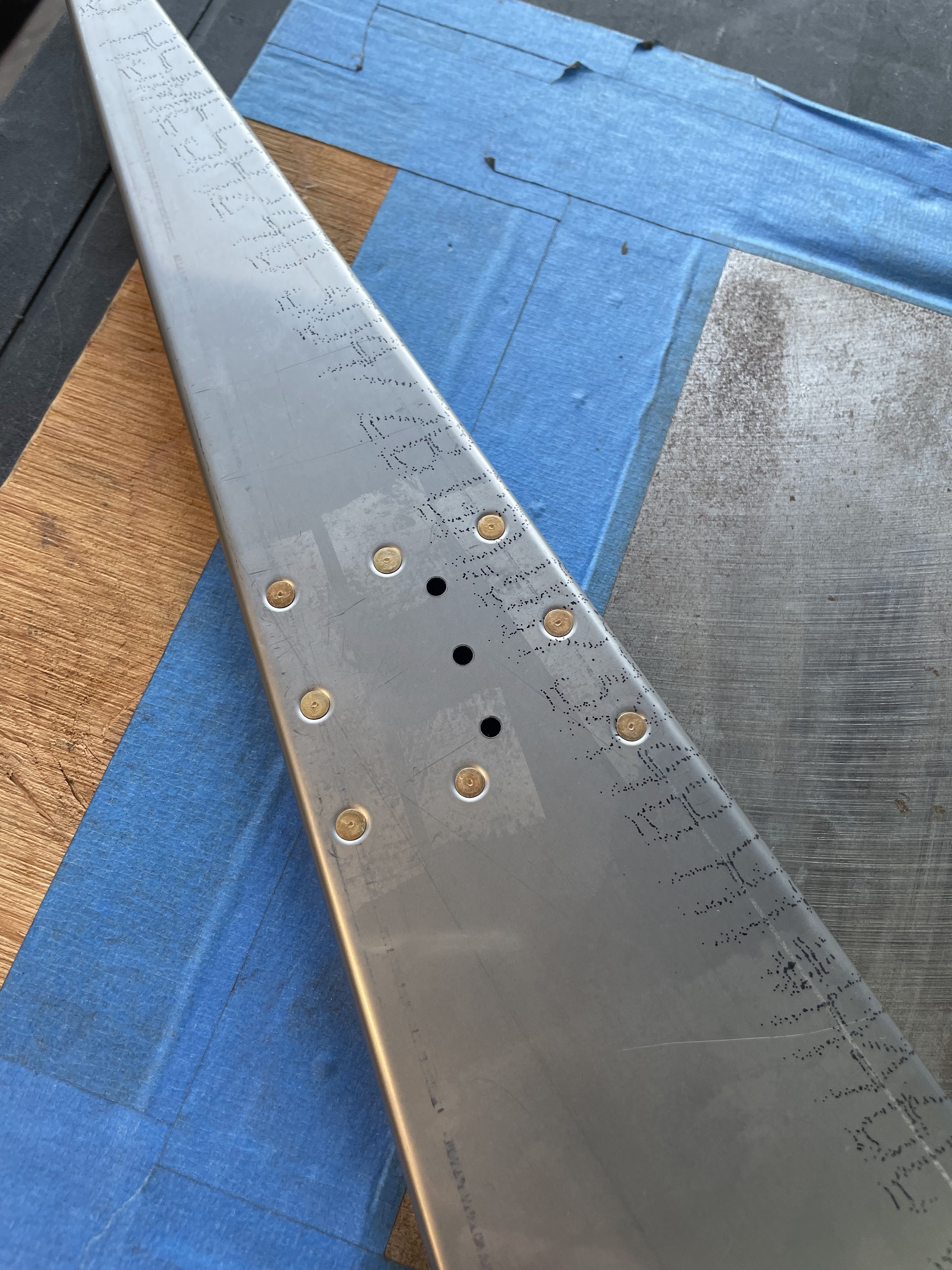
This section went amazingly fast, I think I completed it start to finish in a few hours which seems like the shortest section to date. I originally had a cheap screw clamp style flair tool that I used for the fuel tanks that I didn't particularly like, and instead invested in a rolo-flair tool for this section based on some research from the VAF forums. The result is a much cleaner looking flair, but after a few failed attempts I realized that it's critical to oil the cone of the tool first or it will leave a very rough surface finish.
Otherwise, I had a cheap harbor freight tube bending tool that worked just fine for this section. Using the provided measurements everything just dropped in and clamped on almost perfectly. I haven't found a way to pressure test it yet, and might just have to do that end-to-end once the tanks and engine are on.


Definitely needed a helper for this section! I had a few tables that the fuselage and tail were resting on. To get the halves to align, what I found to work best is to block up the tail at two points with an assortment of scrap wood with a plywood sheet on top to match the angle of the skin so I didn't accidentally bang a notch into the tail section. After some shimming, I was able to get it pretty much exactly aligned so I could just slide the tables together and they would mate precisely. When doing this just have someone check both sides that all the side skins are lapping in the correct stacking, and that the bottom tabs don't get smashed or bent while finessing the two halves together. It takes a bit of pulling and light shaking to get them to snap together, and I can definitely see something getting bent if they're not overlapping correctly first. Everything aligned beautifully once you can get the dimples to match up and snap together. I'm still amazed that Vans can engineer the tolerances to be as tight as they are, especially with such large parts with stacking materials.


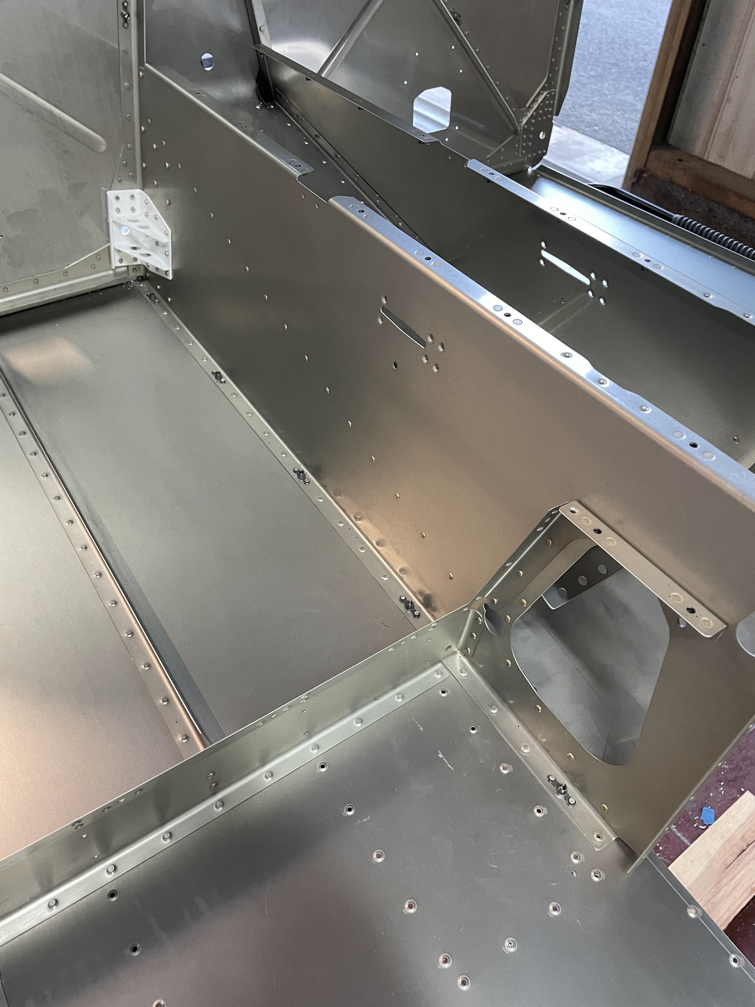
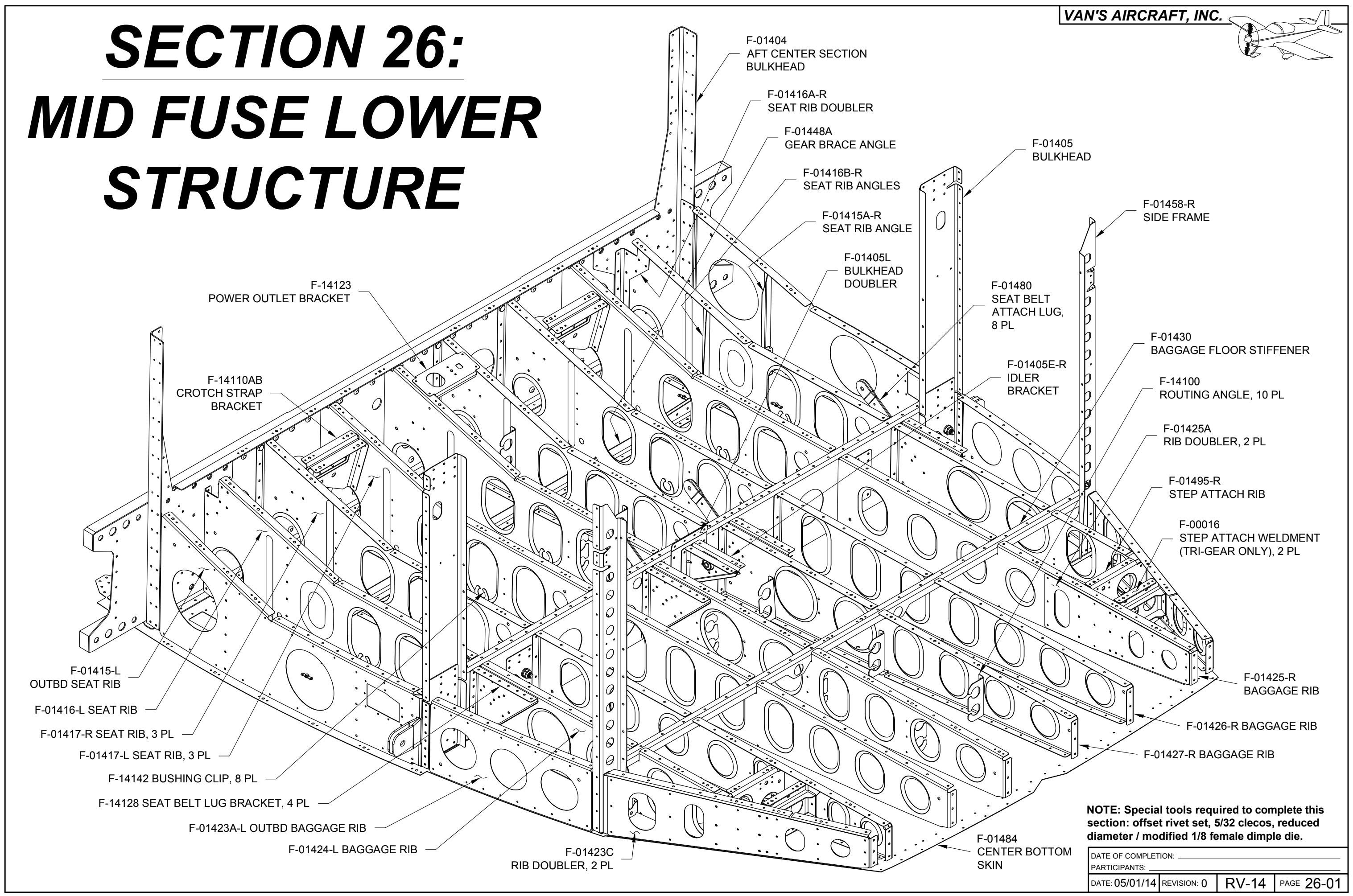
This section was pretty massive, and admittedly took me probably a few months of casual weekends to complete. In fact, it's still not complete, as the vents on the very last step I'd like to color match with the exterior paint, and will probably not attach them until the very end of the build. First up is bolting up a section of 2x4 to one spar to stand the whole assembly on its side to work on the bottom skins. I used a rattle-can self-etching chromate primer on overlapping regions of skin because I didn't want to break out the spray gun and mix paint for this one-off operation.


Getting the center side plate, upper drag fitting, and side skin riveted together was a tad more challenging than expected. Back riveting seemed the obvious choice of method here, however, driving AD4 rivets through a large and heavy piece made it very difficult to keep the assembly flush and tight against the back rivet plate. What ended up happening if I laid everything flat on a table is that the manufactured heads would protrude from the skin just enough to be unacceptable, and I had to drill them out. My solution was to purchase a long reach c-clamp from harbor freight to reach all the way to the drag fitting and clamp the assembly tight against the underside of the table supporting the back rivet plate. This worked great, and the rivets were now perfectly flush.


Installing the bearings on the control column. Had to trim the powder coat a bit to get the bearings to fit, but otherwise everything lined up here perfectly.


Cutting notches in the longerons and various other parts were done with a basic cut-off wheel from a high-speed rotary tool. Just go really slow so as to not have the tool jump. Bending the longeron took some significant twisting. I think I had to bend the assembly almost 360 degrees to achieve the 10 degree permanent twist. This took me some time to work up to as I was afraid of folding the aluminum channel, but it's surprisingly robust.


Cutting the roll bar angles was done with a band saw then primed.


Assembly is pretty straightforward and access is pretty good. I was able to drive almost all of the rivets solo, except for the lower corners of the fuselage. Some of the rivets, especially around the intercostals were tricky to get t, and I found that I was having to be quite creative with my collection of bucking bars to get into tight spaces.


I elected to install a custom canopy latch from JD Air and it seemed appropriate to do this now while everything is accessible, but in really it probably doesn't matter since the fuselage side is always going to be accessible. The install involves printing a template and cutting out additional material beyond the pre-cut slot from the factory handle. I used a rotary cut-off wheel for most of this, then used a hand file to get it to final size. I went super slow here, since I was aiming for as tight a tolerance as possible given that any gaps are going to be exposed to the elements right next to you in the cockpit. The only thing I didn't like about the install is the single rivet hole between the two sections of the handle. The instructions say to dimple and put a dummy rivet in, but then you have to drill out material from the handle to accept the protruding rivet. Instead, I decided to just fill the hole with an epoxy filler and keep it flush. I suppose the worst thing that could happen is that it breaks out eventually.
I did decide to drill a hole into the bracket that will insert into a slot on the underside of the handle, presumable to accept a locking bolt. I'm not sure if I plan to actually install a canopy handle lock, but if I can find a design I like it would go below the handle and raise a bolt through the underside of the assembly.


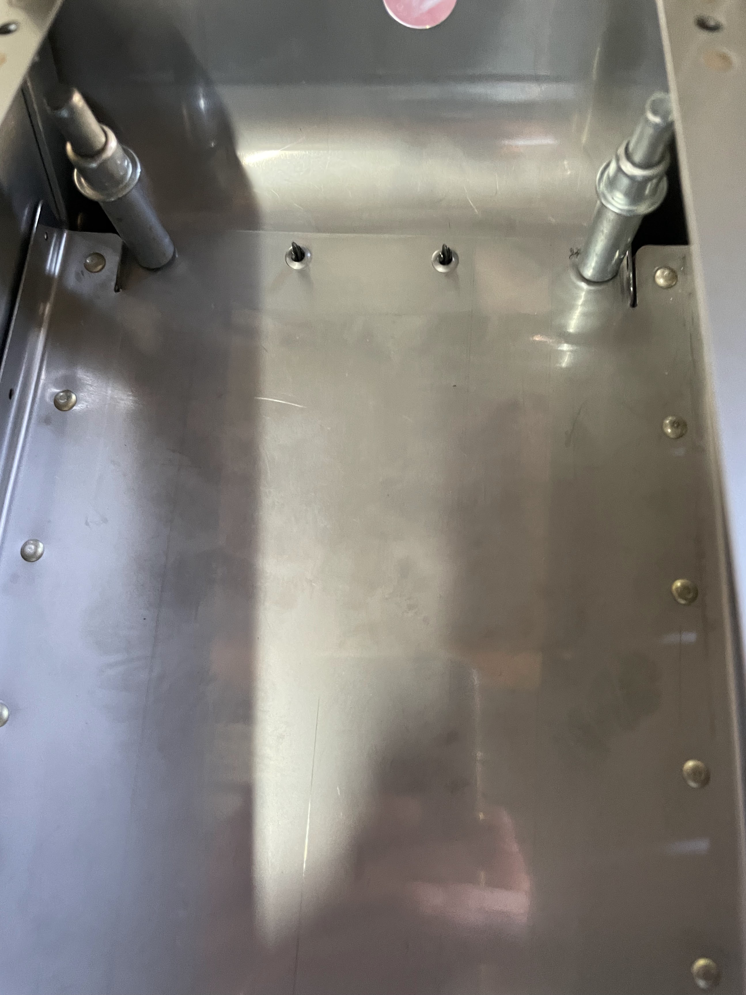
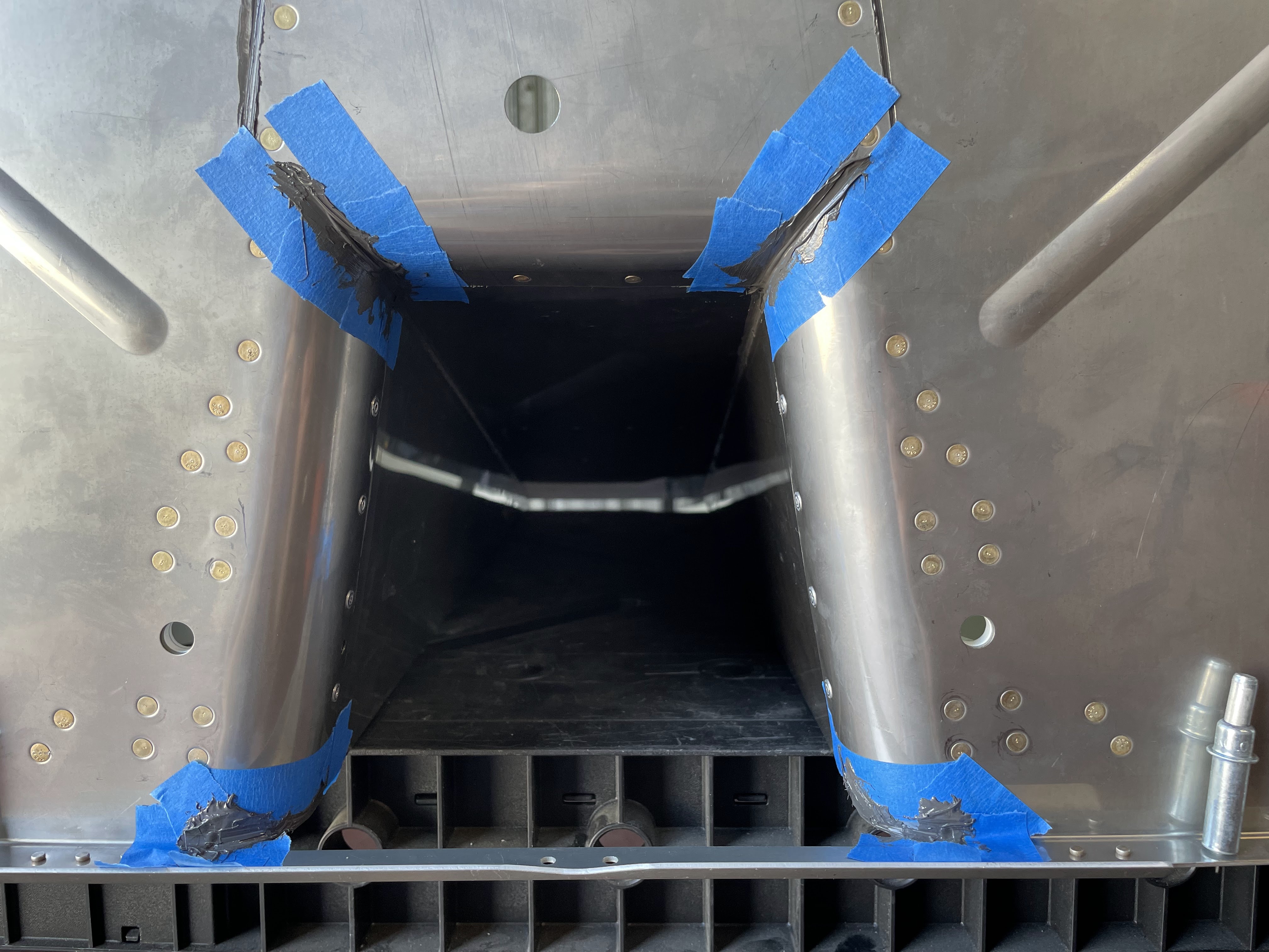
Lastly was sealing up all the seams and holes around the firewall and mating surfaces with proseal.


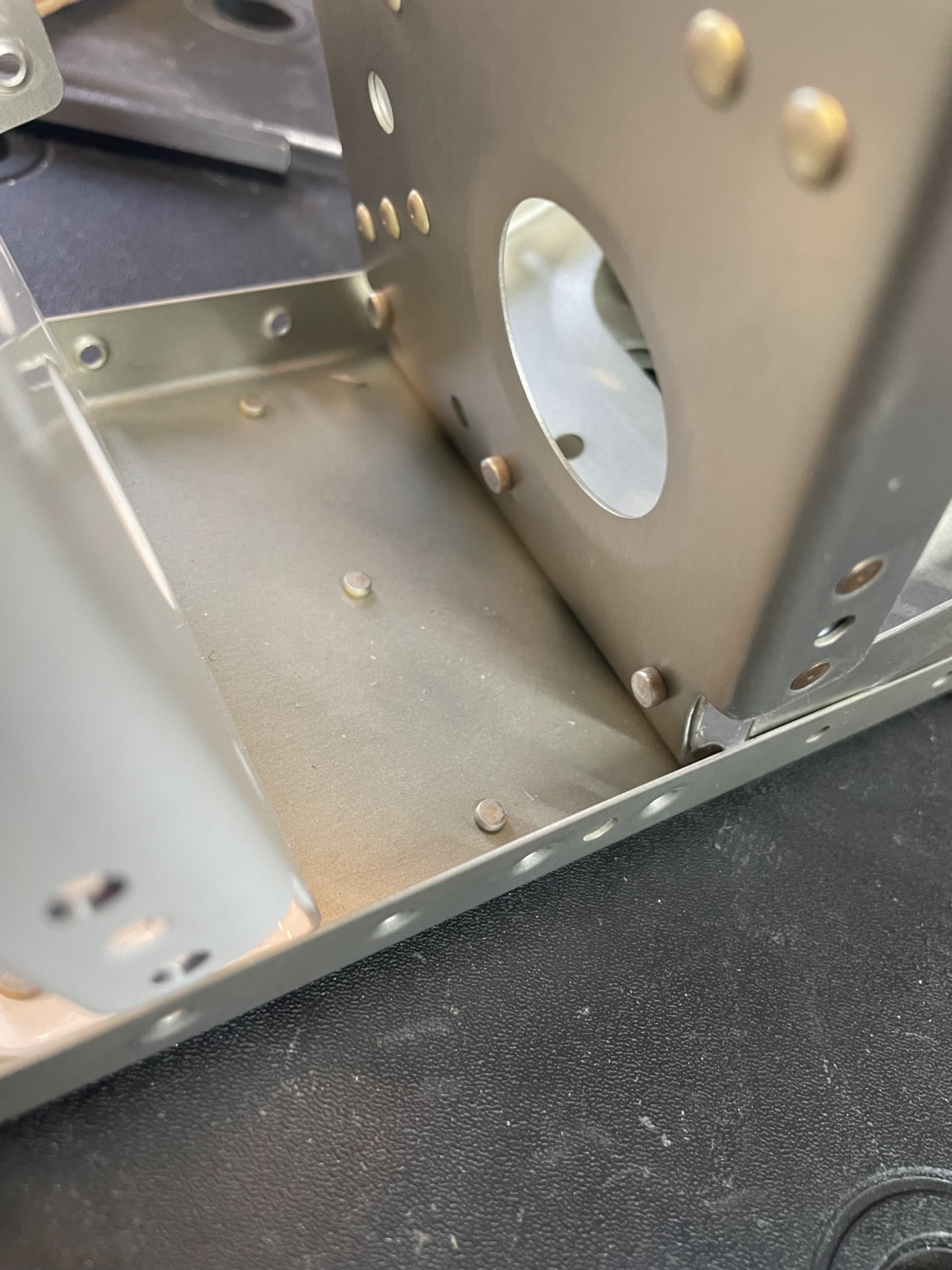
In general the firewall sections didn't have too much complication. Applying tank sealant to all the seams was a bit of a pain, but not particularly difficult after building the fuel tanks. The hardest part was probably getting the bends for the stainless steel sections at the tunnel entrance to align and lap correctly. Once attached together, the parts are very stiff and difficult to manipulate, and it actually required quite a lot of pushing and bending to get everything to align right. Once it all snapped in place the fit was actually pretty good, but the clecos were somewhat insufficient to hold it all together. I had to create a few shims with #30 holes to keep the clecos from pulling out on the curved section of the tunnel while setting rivets. Otherwise, the only modification was to leave out the exhaust brackets since I elected to use the EXP119 engine, and instead I just put blank rivets in the holes that would normally hold the steel brackets. I kept the doublers behind them, however, figuring they still provide some rigidity and structure.


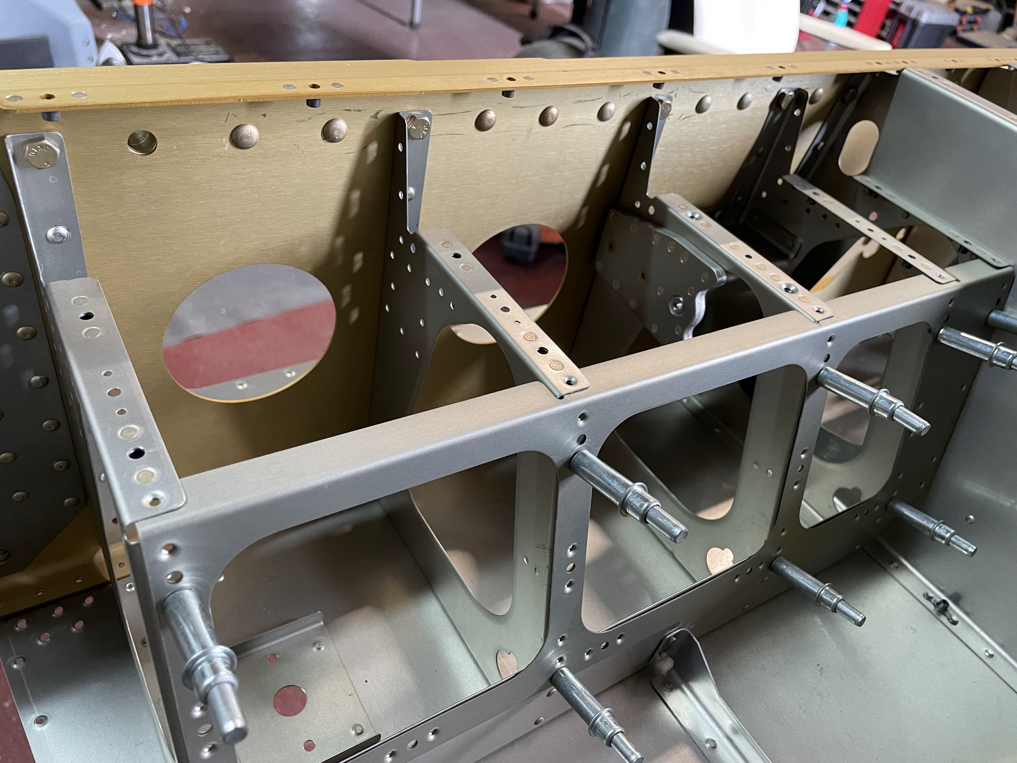
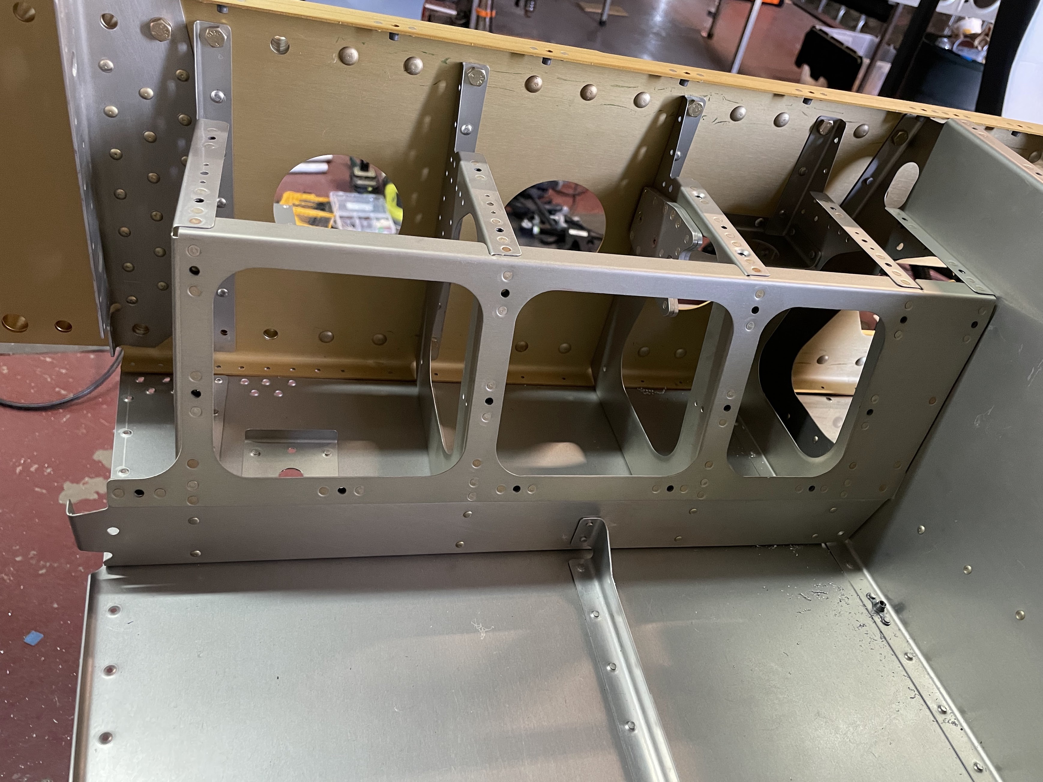
I've found that spending the time upfront to make sure that all flanges are at their proper angles, and that all fluting is performed such that hole patterns line up exactly without preload has saved a ton of time dealing with it after parts start getting assembled. Here, the outermost ribs follow a curve to follow the contour of the fuselage that needs to be carefully fluted to match the hole pattern in the bottom skin.


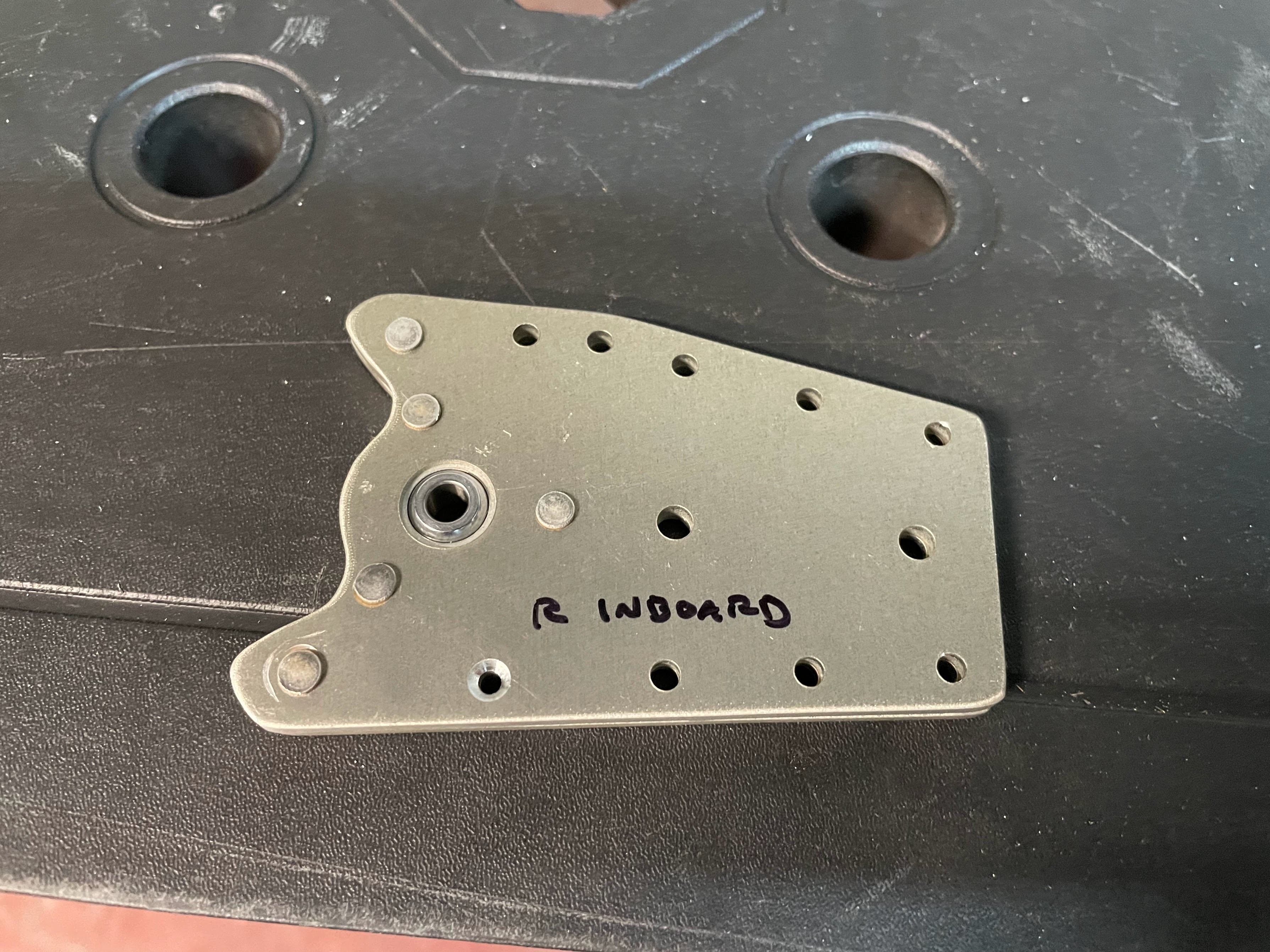
The idler bracket gave me some trouble, given that a 45 degree bend has to be made on the diagonal edges very close to the edge on relatively thick material. A hand seamer was simply unable to make this bend without either badly scarring the material, or resulting in a bed that is not at all sharp. Instead I fabricated a bracket out of angle aluminum as a backing plate, clamped the assembly down to a table, and used a combination of the hand seamer as well as hammering the edge to form the bend.


Next is priming, dimpling, and riveting on various doublers and stiffeners to the bottom skins. Everything here was back riveted and straight forward.


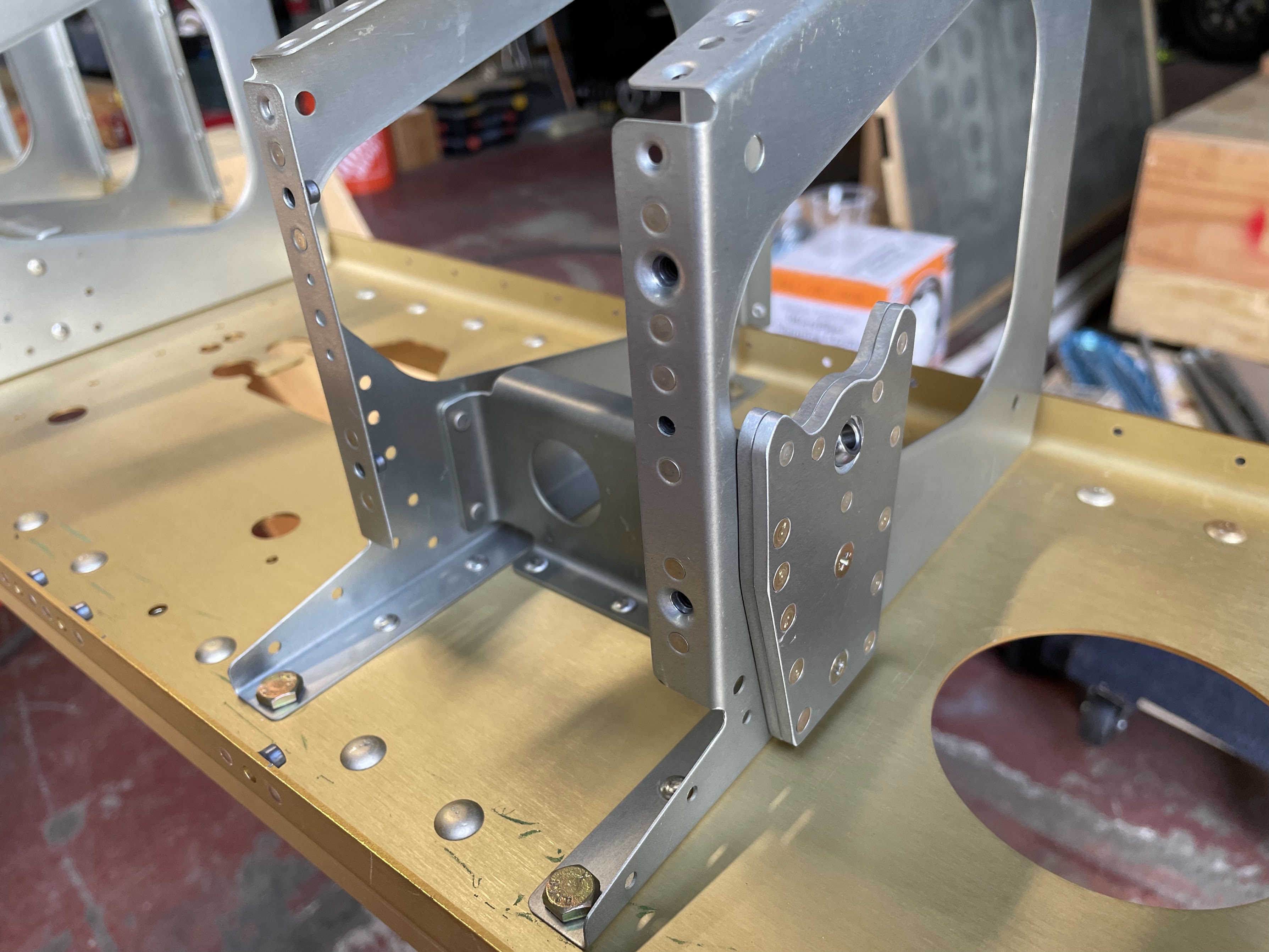
The step brackets are attached at an angle, and were a bit of a challenge to set some of the rivets, particularly the AD4- rivets in the corner. Here the tiny tungsten bar with angled sides came in handy, but still a challenge to drive and buck.


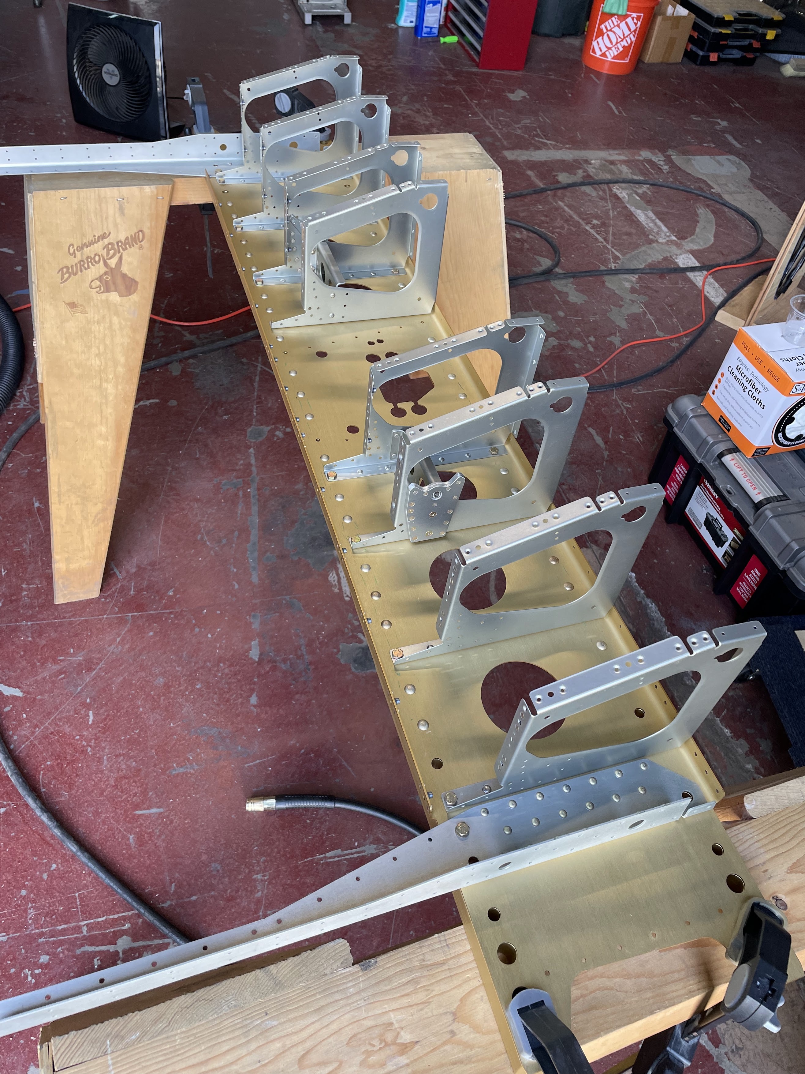
The mid-rib gear brackets are each attached with 3 AD 4- rivets that need to be aligned perpendicular to the bottom skin. I used a rafter square here, and checked/adjusted after every rivet.


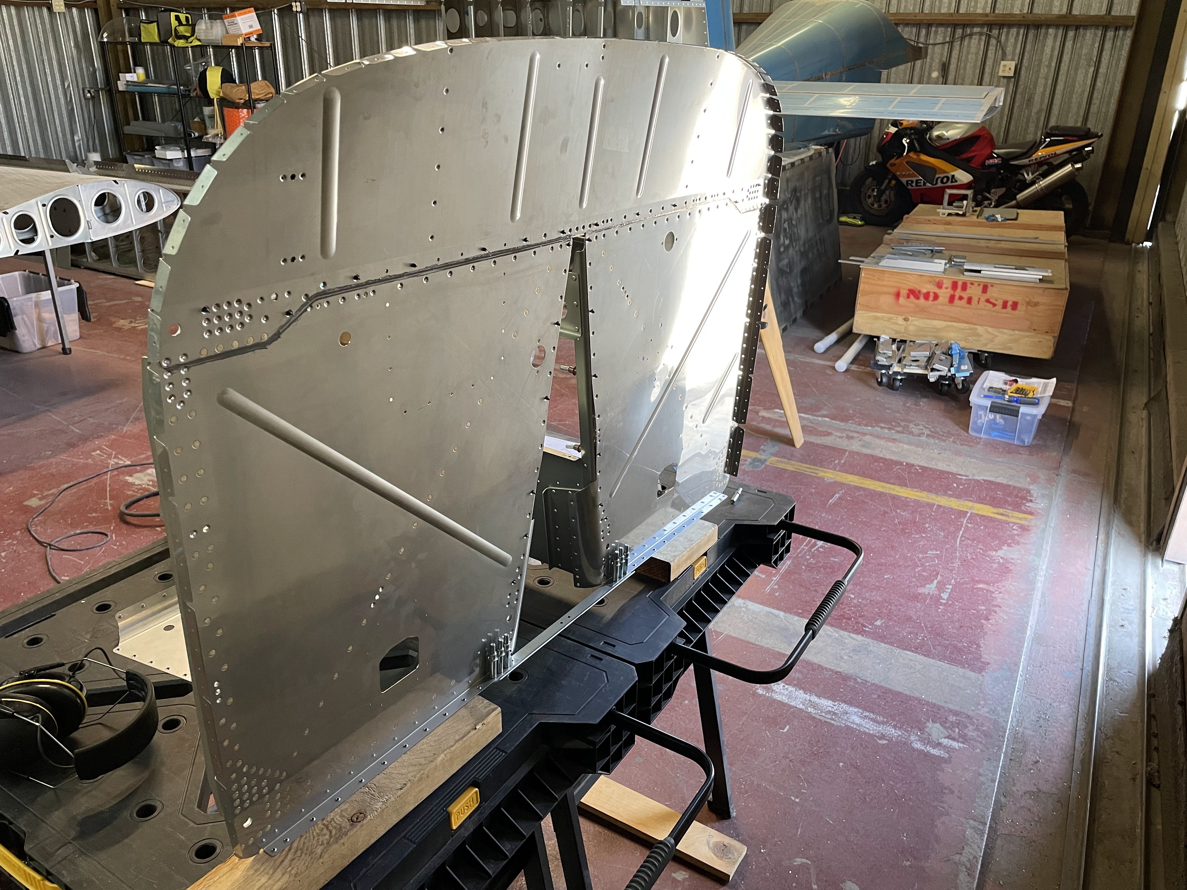
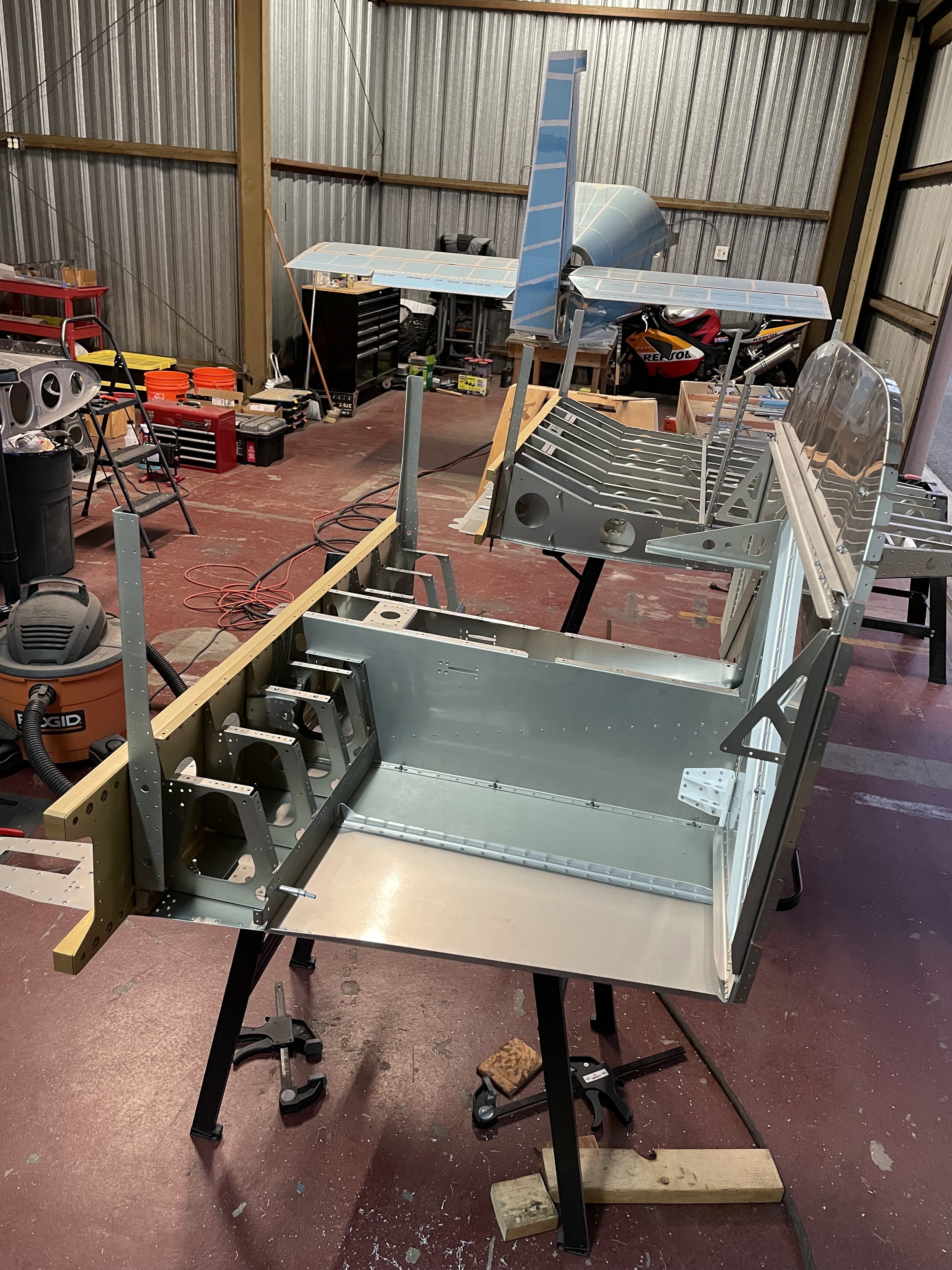
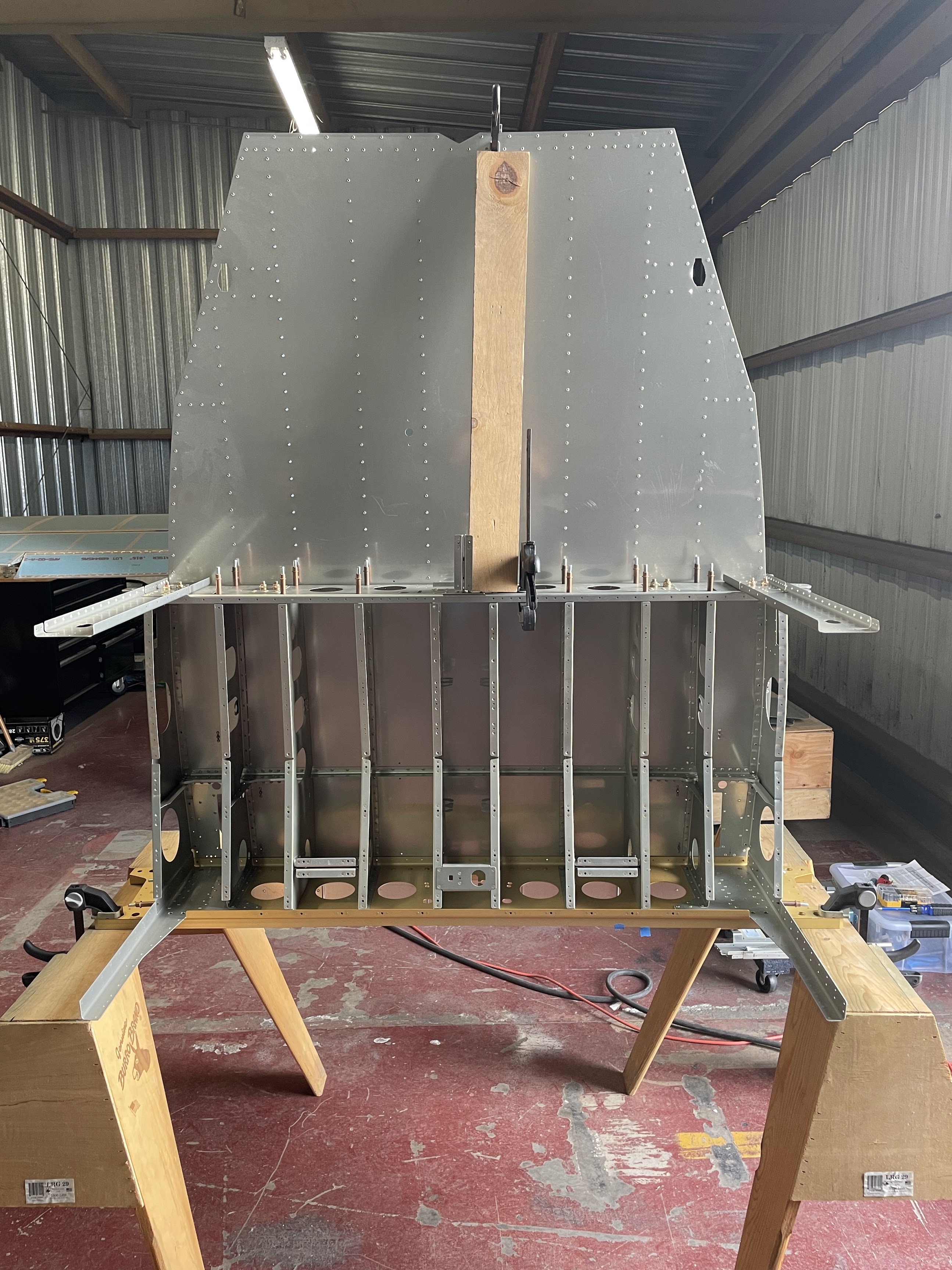
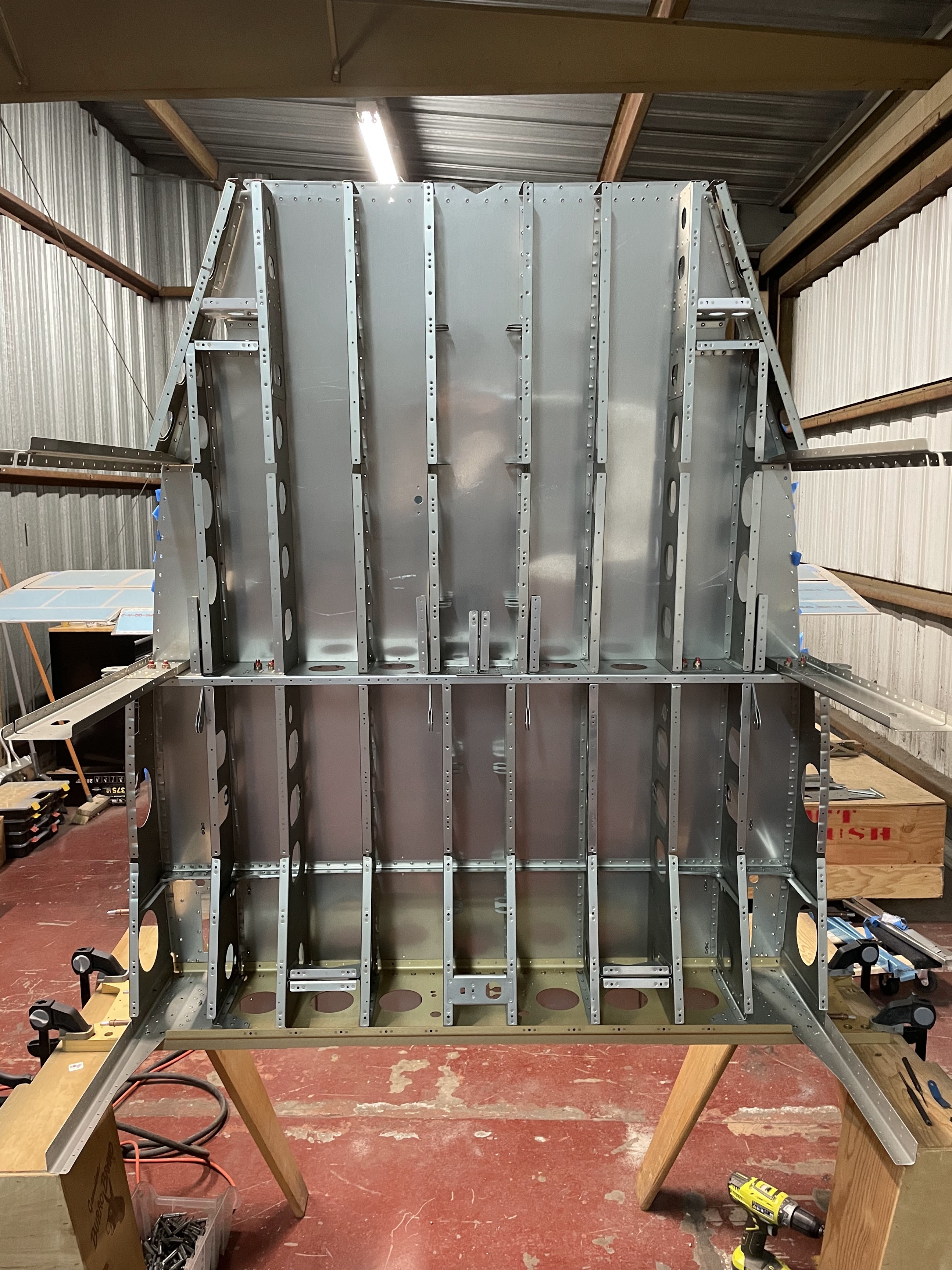
When starting to attach the aft ribs, it was easier to set the whole assembly vertically by clamping the spar flat against a table or pair of sawhorses. This made the aft skin fairly floppy to start as there was nothing to support it, so I just clamped a piece of wood to it to keep it flat while attaching ribs. This put everything in a fairly accessible position to rivet. I ended up doing much of this single-handed, but the rivets near the center definitely require two people.


Finally get to break out the pretty gold anodized center spar sections! Everything here was pretty basic given that there was easy access to rivet components onto the spar. The only place it got a bit tight is in trying to tighten and torque the bolts for the bearing bracket. There's a screw head on the bolt, and not a lot of room to squeeze in there unless you have a stubby screwdriver.
Lastly for reaming the bolt holes for the rear spar brackets, I drilled a block of wood with the final size dimensions using a drill press and clamped it to the part as a guide to keep the reamer perpendicular.